Printing Process and Quality Improvement
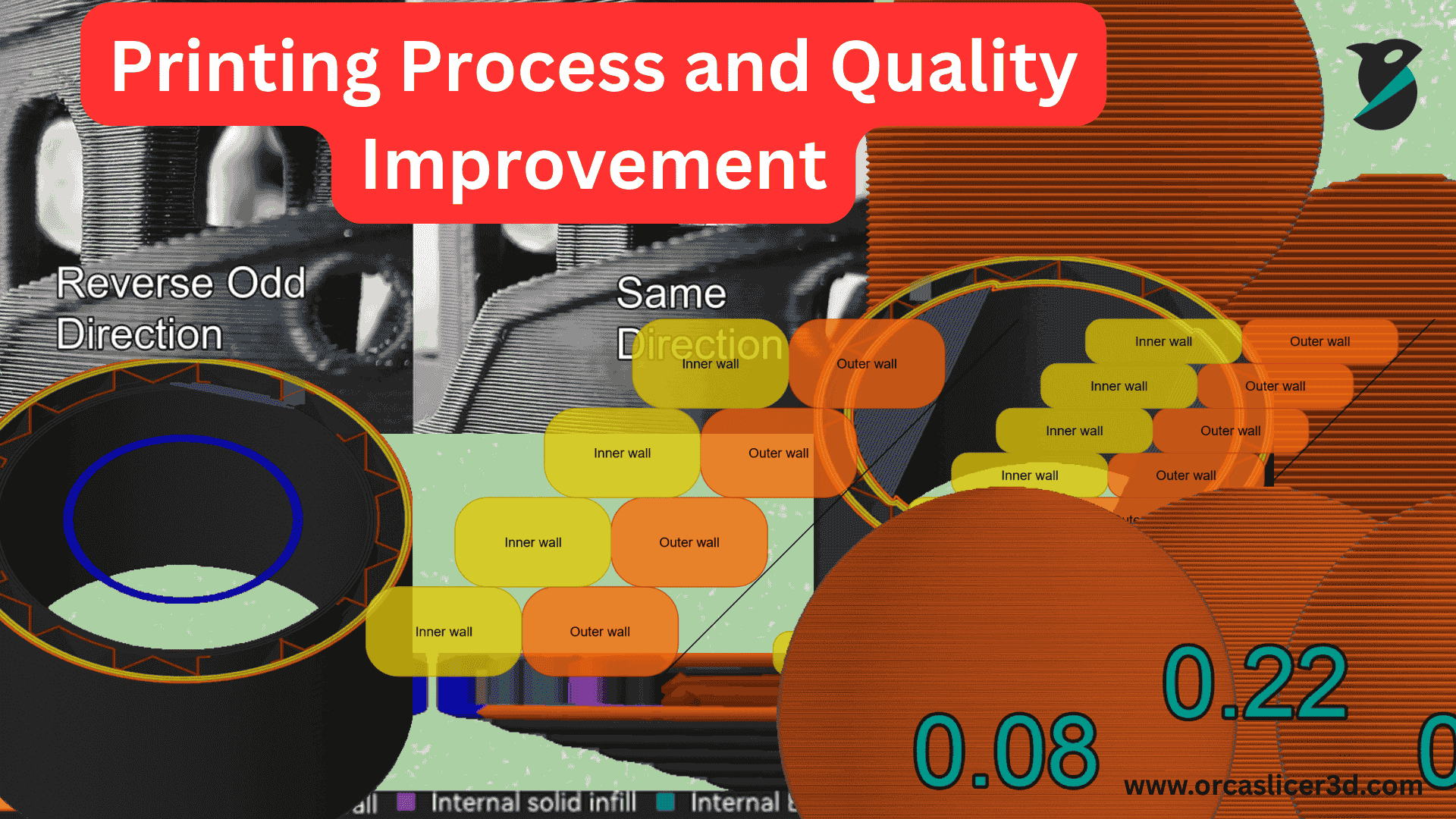
Quality Settings manage how smooth, strong, and accurate your print will be. These quality settings prepare a compromise between professional appearance and perfect fit on the one hand, and fast printing times and less certain performance. Orca Slicer gives you many quality settings to excel a layer of your print to get the most satisfying result. Precision settings keep your size and smooth out the surface. It includes feature settings such as gap closing, resolution, as well as a compensation instrument to eliminate tiny printing mistakes. This will provide you with perfect edges and shapes.
🎯 Precision Settings
Precision settings keep your size and smooth out the surface. It includes feature settings such as gap closing, resolution, as well as a compensation instrument to eliminate tiny printing mistakes. This will provide you with perfect edges and shapes.
📏Layer height 3d printing orca slicer
Height of layer is how thick each printed layer will be. More and smaller teams provide more information but take up more time. Fewer, thicker layers are less detailed but develop faster and have a more even surface. The first layer is thicker to stick.
➿ Line Thickness
Thickness of the line is determined by the width of the melted wire. The correct width ensures that the pieces join together quickly and do not break. If style is too small, it may be fragile or have holes. If the surface is too thick, it may appear rugged or bulky. The wall, fillings, and top parts of the print can all have separate line widths for increased quality.
🧱 Wall and Surface Settings
Web page settings determine which wall is printed first and in what direction. When the inner wall is constructed first, it improves the bridge quality, whereas when the outer wall is the final, the finish is smoother and softer. The design also features designs that determine how much material is applied to the top of the web page.
🌉 Bridging Settings
Bridge setting is needed so that the printer can print across the empty bridge. By adjusting bridge density, flow rate, and fan speed, filaments will not strain, and the bridge will be smooth and level. More connections and more upper-surface stringing are provided by more layers.
🧾 Placement and Overhangs
Placement determines the angle before printing or tending to concave. Smaller layers and design features enable you to print a more vertical congested bridge. Wash would not occur if this approach were covered or the print cycle would be balanced.
Precision Settings:
Precision settings help improve the accuracy and overall quality of your 3D prints. By tuning these options, you can reduce visible artifacts, correct small dimensional errors, and achieve smoother, more reliable prints.
Slice Gap Closing Radius
This determines whether small gaps or cracks in the surface of your model are filled when slicing.
If two model edges are closer than 2 x this radius, the slicer fills in that space for you.
✅ Smaller values mean retain higher resolution and more detail.
⚠️ Higher values will fill in more gaps, but may affect the surface detail or precision.
Resolution
Resolution determines the level of detail in the G-Code path, which your slicer converts your 3D model into printable instructions.
Lower numbers = higher resolution, smoother edges, takes much longer to slice.
High values = fast slicing but less detailed.
💡 Tip: If your computer is slow or if it’s a very large model, you might want to increase this value further to slice faster without much affecting print quality.
Arc Fitting
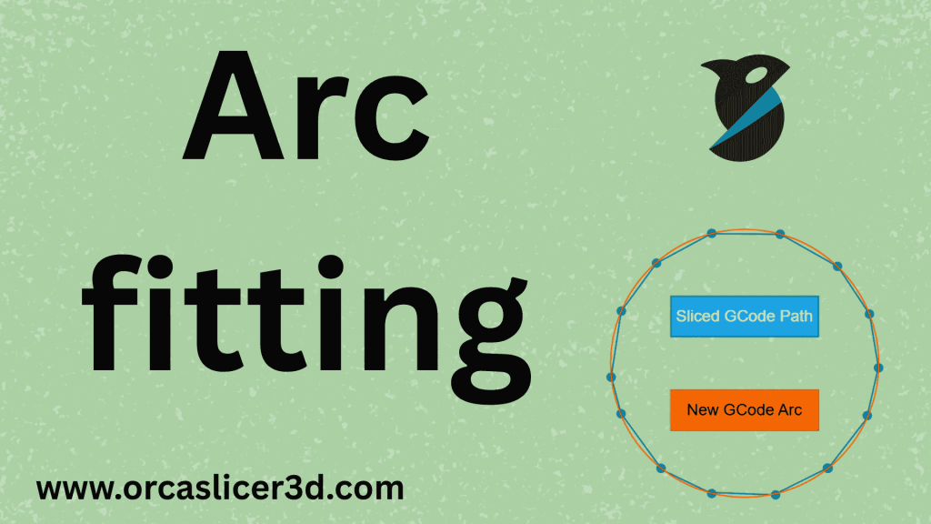
Arc fitting is to replace small straight line segments with smooth curves (Use G2 and G3 commands) in the input NC code.
This interface allows printers to move more efficiently, particularly with printing curved or round surfaces.
Benefits:
Generates more flowing curves and movements smoother.
That is why we made you a great tool for reducing the size of your images.
⚠️ Note: Only works for printers that understand G2/G3 commands.
This option should be turned off for users of the Klipper firmware as Klipper also breaks arcs back down into tiny lines and this can reduce quality.
X–Y Compensation
This config scales your model in the horizontal plane (x and y axes).
It is useful to correct minor defects due to material expansion/ shrinkage or printer calibration imperfections.
Higher values: Slightly increase overall size.
Negative: Make the model a little bit smaller.
💡 Tip: To determine the best compensation value for your printer and filament, use these calibration cubes.
Elephant Foot Compensation
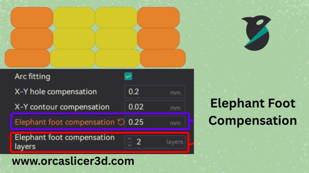
The “elephant foot” effect occurs when the first few layers splay out and are broader than the rest.
This can occur due to:
- High bed temperature
- Excess pressure at the bottom-most layers
- Incorrect bed leveling
You can rectify this by decreasing the width of the first few layers, and Orca Slicer lets you do just that!
Putting in a negative distance will cut down that layers; basically, you can make it sharper and more accurate.
💡 Recommended: Begin at a low value (like −0.1 mm) and then change it depending on your prints!
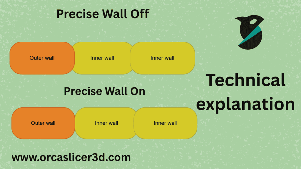
Precise Wall
Precise WallThe distance between the inner and outer walls will be further widened, producing a more accurate hollow distributed structure from the inside outwards.
This does not allow to push the outer wall out when an inner wall is printed next with it.
If No Wall: Outer walls can warp in and cause the part to be too big.
With Precise Wall): Layers stay cleaner, dimension remains more accurate, and features are less warped.
✅ Best for models that require tight tolerances or clean outer surfaces.
Precise Z Height
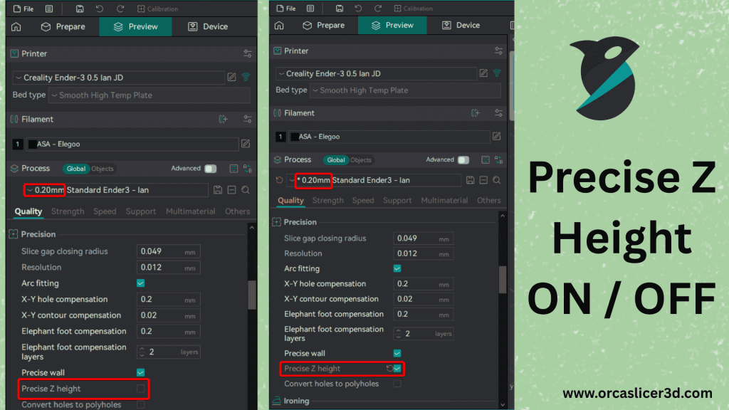
This feature guarantees that the final print height will be consistent with the model’s designed height — in case its not an exact multiple of layer high.
Example:
If your model is 20.1 mm in the Z axis and you are printing it at 0.2 mm Layer height Settings, then standard slicing would yield a printed height of 20.2 mm.
With Precise Z Height the last two layers are shaved off a bit so that exactly 20.1mm will be reached in the end.
✅ Provides you with precise model dimensions and smoother top surfaces.
Polyholes
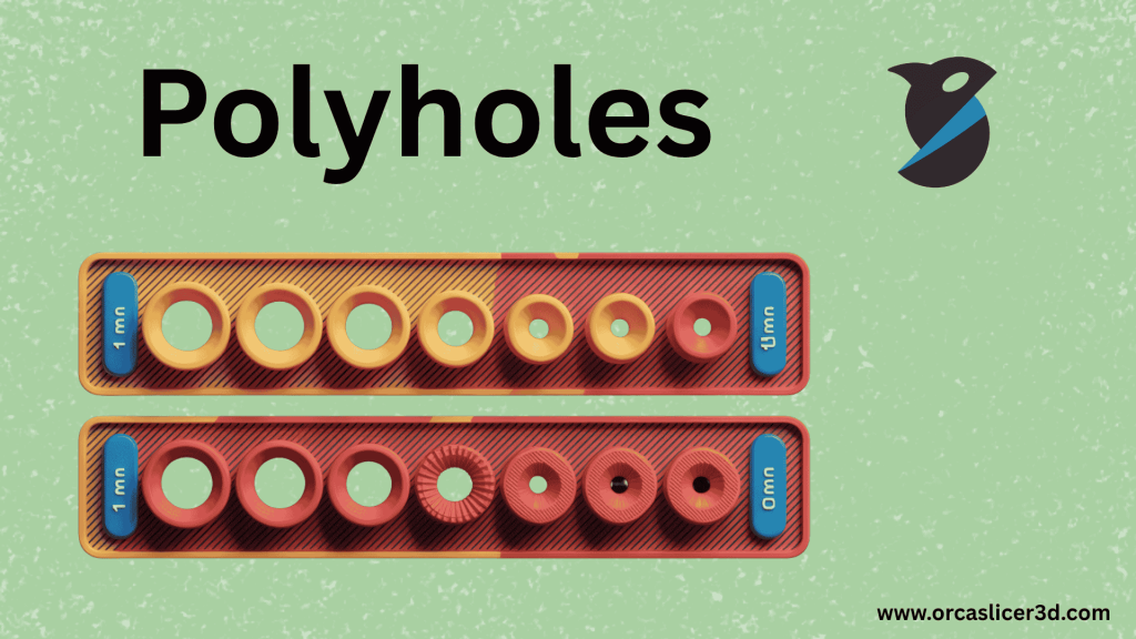
Polyholes enhance the precision of round holes in 3D printed objects.
Printers render using straight lines, and these perfect circles can become a bit not quite round.
This feature substitutes circles with small polygons of straight lines, and the holes are made to be printed more accurately in a proper size.
💡 Best for models with lots of screw holes or round openings.
Summary
| Feature | Purpose | Result |
|---|---|---|
| Slice Gap Closing Radius | Fills tiny cracks or holes | Smooth, gap-free surfaces |
| Resolution | Controls model detail level | Smoother or faster slicing |
| Arc Fitting | Replaces lines with arcs | Cleaner curves and smaller files |
| X–Y Compensation | Adjusts horizontal size | More accurate part dimensions |
| Elephant Foot Compensation | Fixes wide first layers | Sharper bottom edges |
| Precise Wall | Improves wall alignment | Better dimensional accuracy |
| Precise Z Height | Adjusts final height | Exact model height achieved |
| Polyholes | Corrects hole shape | Rounder, more accurate holes |
In short: Fine-tune settings: That’s critical for clean, accurate and professional looking parts.
Well-tuned, they help make every print match the intended design perfectly — all-printed walls should be smooth and flawless, printed parts should have precisely the right size once assembled and details should.
Layer Height 3d Printing Orca Slicer:
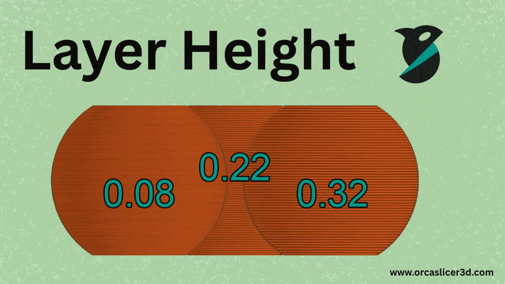
How smooth and professional an object looks in 3D printing is highly dependent on Layer height 3d printing. It is the Tech Neck width, or rather the vertical thickness of each layer that the printer builds, one at a time. Layer height plays both roll on printing speed and final result. Finer layers produce more-detailed, smoother prints; thicker ones print quicker but can look rough or display visible lines.
Using Orca Slicer you can simply control layer height in the Quality tab, Prepare menu. Tuning this setting just right helps you scale time, surface quality, and sturdiness for each print.
Importance of Layer Height Settings and Adjustment
“The average person talks about materials or settings like temperature, but it’s just as much about layer height,” he says. With the correct layer height, you get:
- Less and/or no visible lines with a smoother surface finish.
- Sharper, more accurate details (especially on rounded surfaces).
- Stronger overhangs (165 F), more stable parts that hang out.
- A print of lesser surface blemishes or distortions.
Layer Height Guidelines
We recommend printing at the perfect layer height given your nozzle size. A good rule of thumb is keep it between 20% and 80% the size of your nozzle.
- Under 20 percent: Flow is not stable, results in weeping or crocodile patterns, especially at high speeds.
- Over 80%: The layers may not adhere to each other well, resulting in weak bonding and print surface quality.
Quick Reference Table
| Nozzle Size | Minimum | Maximum | First Layer Height |
|---|---|---|---|
| 0.2 mm | 0.04 mm | 0.16 mm | 0.12 mm |
| 0.3 mm | 0.06 mm | 0.24 mm | 0.18 mm |
| 0.4 mm | 0.08 mm | 0.32 mm | 0.25 mm |
| 0.5 mm | 0.10 mm | 0.40 mm | 0.30 mm |
| 0.6 mm | 0.12 mm | 0.48 mm | 0.35 mm |
| 0.8 mm | 0.16 mm | 0.64 mm | 0.45 mm |
| 1.0 mm | 0.20 mm | 0.80 mm | 0.55 mm |
First Layer Height
The first layer is the basis of your print, so its height makes a difference. A tad thicker primary layer to ensure adhesion to the bed and help contact with the bed surface, exploiting even small irregularities.
Recommended: 0.25 mm on a 0.4 mm nozzle (roughly 62.5% of the nozzle diameter).
Maximum: Approximately 65 percent of the nozzle diameter.
A good first layer ensures the rest of your part will print better, stay on the bed surface.sion.
Layer Height and Overhangs
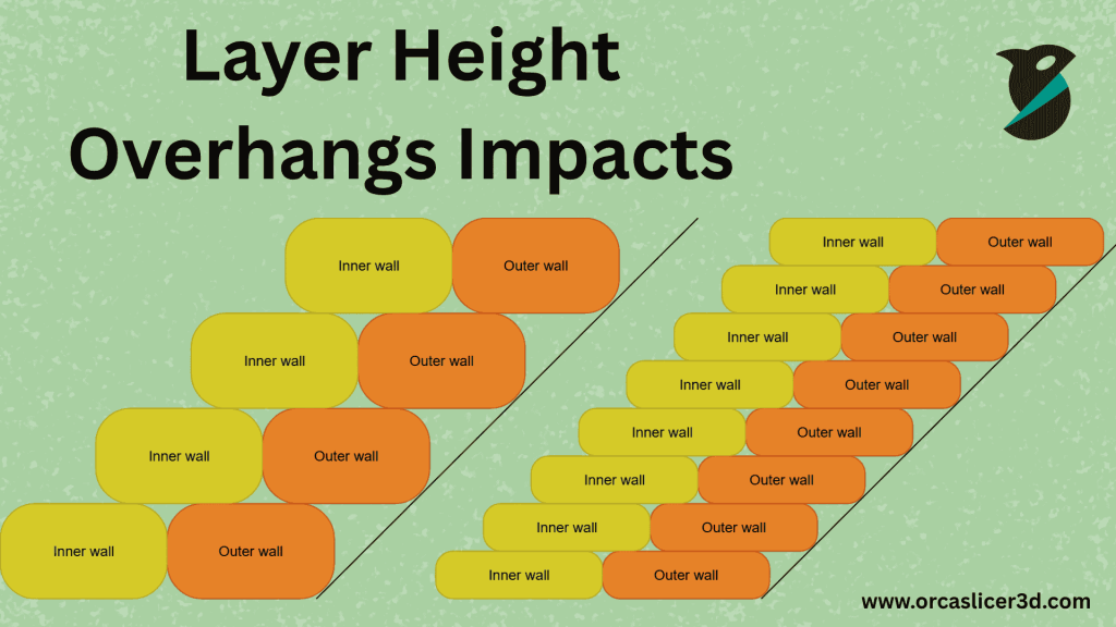
And what about how your printer handles overhangs parts that extend outward with minimal or no support, even from the print beneath it?
- Less Layer Height: Allows to print steeper overhangs more cleanly, thanks to the fact that there is less distance between each layer.
- Higher Layer Height: Less layers make the print become more arrow-like or needs more support under a lower angle.
Hence a finer layer height will result in more-sculpted curves and better overhangs, whereas a thicker layer height is perfect for faster but less detailed prints.moother curves and stronger overhangs, while a thicker layer height is better for faster but less detailed prints.
Layer Height in Orca Slicer
In Orca Slicer, to change your layer height, navigate to the Prepare tab and then Quality Settings. You can:
- Choose a Layer Height in millimeters according to the level of detail your model will require.
- Tune the First Layer Height to be 20-80% of the nozzle size.
- Adjust other print settings as desired before starting your job, to achieve the best compromise between speed, detail and surface finish.
Summary
You might think layer height is a small setting, but it has a huge influence on your print’s appearance and strength. With the best value right on your nozzle size and print type selection, you can add smoothness, strength, and precision to all of your 3D prints on time.
Line Width in 3D Printing
Line Width is that width of the strands of filament as they come out of nozzle of the printer. It’s one of the most important quality settings in Orca Slicer as it has direct impact to strength, surface effect & preciseness of your 3d prints.
If your line width not adjusted well, the filament will have many bad effects on prints, such as weak layer bonding, gaps in solid surfaces or deformed walls.
Lines that are too thin create a fragile print and cause empty spaces in between the layers.
Lines that are too thick result in excessive fullness, loss of thin details and surface “bumps” or “blobs.”
Adjust line width and you print strong parts smooth in minimum time!
Line Width Settings:
It is possible to define the line width in two ways in Orca Slicer:
- Fixed value (millimeters) — You manually type the width in mm.
- % Of nozzle diameter — software will set line width settings automatically based on the borders of the users create.
Percentage is better, as it updates line width by itself, whenever you switch nozzle size. This also ensures a consistent print quality without additional manual adjusting.
You can read more on the flow math here: Flow Math.
Recommended Line Width Values
I suspect a good beginning is to make the line width of 100% nozzle diameter.
Here’s what impact we can see by varying these sets of values:
- 100% width nozzle: Best compromise between quality and accuracy.
- Not 100%: Will result in poor binding and gap lines.
- 100%–150%: Produces stronger parts with increased layer adhesion.
- 150% and higher: May lead to over extrusion, rough surfaces or dimension errors.
Thicker lines (100-150%) will probably suit the robust prints, especially the inner walls and infill.
On 100% the filament line is a bit thinner at the beginning, but then perfectly stretches to match nozzle size when it’s pressed onto previous line.
Benefits of Thicker Lines
Increasing line thickness will:
- Upgrade your print strength with better layer bonding
- Aid internal features (such as infill and inner walls) to solidify
- Cut down on printing time as you cover more ground per line
However, too thick lines produce overflow and do not bring out small details, so don’t overuse them either.
Line Width Types in Orca Slicer
In Orca Slicer, you can set different line widths for specific parts of your print under the Quality tab. Each type plays a unique role:
| Line Type | Purpose | Recommended Width |
|---|---|---|
| Default | General fallback value when no specific width is set. | Auto (Set to 0) |
| First Layer | Slightly wider lines help with bed adhesion and fix uneven surfaces. | Wider than normal |
| Outer Wall | Controls the outer surface look and accuracy. | 105–120% of nozzle |
| Inner Wall | Adds strength to the model’s structure. | ≥120% of nozzle |
| Top Surface | Affects the smoothness of the top layers. | 100–105% |
| Sparse Infill | Fills large inner spaces without wasting material. | ~115% |
| Internal Solid Infill | Builds solid top/bottom layers. | ~110% |
| Support | Creates support structures that are strong yet easy to remove. | 100% |
These separate controls let you fine-tune every part of your print for both beauty and durability.
Summary
Line width might look like a small setting, but it has a big impact on the strength, accuracy, and appearance of your 3D prints.
By starting at 100% of your nozzle size and carefully adjusting each line type in Orca Slicer, you can achieve prints that are strong inside, smooth outside, and consistently high in quality.
Seam Settings in Orca Slicer:

A 3D printer creates a model by building it layer by layer. Each of those layers has a beginning and an end. This point is called a seam. Spiral “vase mode” prints don’t have seams because they are printed in a single continuous spiral. But nearly all other prints do have seams, so controlling how the seams look and where they go is crucial for surface quality and strength.
In Orca Slicer, seam control has two big parts:
- Seam Position (where the seam goes)
- Modifiers (how the seam behaves and looks)
You’ll also find extra tools like scarf seams, wipe settings, and troubleshooting tips to make seams cleaner and more consistent.
1) Seam Position
Choosing the right seam position helps you hide the seam or make it cleaner. It can also improve strength by spreading weak points.
Main options:

- Aligned
Tries to line up the seam on a hidden internal facet so it’s less visible. - Aligned Back
Combines “Aligned” and “Back.” It prefers hidden spots away from the front of the model. Great for figures or objects with a “front view.” - Nearest
Puts the seam close to where the nozzle last stopped. This reduces travel time and is good for speed with acceptable strength. - Back
Always places the seam at the back of the object (minimum Y on that layer) to keep the front clean. - Random
Scatters seams around the model. This spreads the weak points, which can increase part strength.
Pro idea: If you need maximum strength, “Random” is helpful because the weak point doesn’t stack in one line.
2) Seam Modifiers
Modifiers change how seams behave to reduce stress, improve looks, or boost water-tightness.
- Staggered Inner Seams
Moves inner seams around (and away from the outer seam) across layers. This spreads the weak points and can improve strength and water-tightness. - Seam Gap
Controls the small gap between the start and end of a loop (mm or % of nozzle).- Larger gap → reduces bulging.
- Smaller gap → reduces visible seam line.
- For a well-tuned printer (with good pressure advance and retraction): ~0–15% of nozzle often works well.
3) Scarf Joint Seam (Advanced Smoothing)

A scarf joint overlaps the start and end of the seam on a gentle ramp, which softens the transition and reduces visible marks.
Why use it (Pros):
- Reduces visible Z-seams
- Looks better on curved surfaces
- Can slightly improve seam strength by smoothing the transition
Trade-offs (Cons):
- Slightly longer print time
- Not as effective on sharp corners or overhangs
- Needs tuning (length, speed, flow) for best results
Scarf Types
- Contour: Applies scarf only to the outermost perimeter.
- Contour and Hole: Applies scarf to the outer perimeter and inner walls around holes.
Conditional Scarf Joint
Automatically uses scarf only on smooth, curved areas (where seams would show the most). Sharp corners keep normal seams to protect accuracy.
Scarf Settings to Tune
- Scarf Joint Speed: Print scarf slowly (generally < 100 mm/s). If this speed is higher than wall speeds, the printer uses the slower one. You can also set it as a % of wall speed (default 100%). Enabling Extrusion Rate Smoothing helps if your inner/outer wall speeds differ a lot.
- Scarf Joint Height: Vertical offset where the ramp begins (mm or % of current layer).
- 0 → starts at the same height as the current layer.
- Example: layer height = 0.2 mm; set 50% (0.1 mm) → scarf starts at 0.3 mm and ramps to 0.4 mm by the end of the scarf length. This smooths the transition and reduces artifacts.
- Scarf Around Entire Wall: Wraps scarf around the full perimeter. Usually off (adds time without big visual gain).
- Scarf Length: Horizontal distance of the ramp. 0 disables scarf. Defaults (like ~20 mm) give smooth blending.
- Scarf Steps: Minimum segments used to build the ramp. More steps = smoother. Default 10 is usually enough.
- Scarf Joint Flow Ratio: Flow during scarf. 100% is normal (recommended). Lowering can under-extrude.
- Scarf for Inner Walls: Applies scarf to inner perimeters (like holes). Usually off unless inside seam quality really matters.
4) Wipe and Cleaning Controls
These tools help hide blobs and make seams more consistent.
- Role-Based Wipe Speed
Makes the wipe move at the same speed as the feature that was just printed. Turn this on for consistent wiping behavior. - Wipe Speed (when role-based is off)
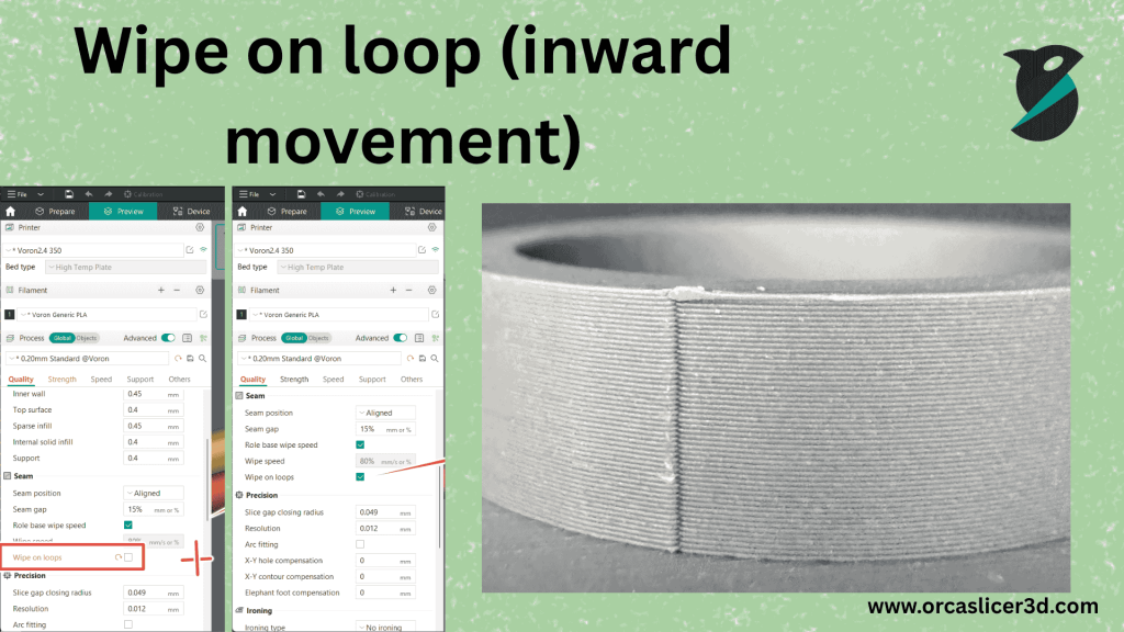
Set an absolute wipe speed or a % of travel speed. - Wipe on Loop (inward movement)
When finishing a loop, the nozzle moves slightly inward into the model. This tucks the seam end, reduces unevenness, and helps clean the nozzle to reduce stringing. Uses your printer/material’s Wipe Distance and retract-before-wipe values. - Wipe Before External
Performs the de-retraction inside the model, just before starting the outer wall. Any extra material comes out inside, keeping the outer surface clean.
This is especially useful with Outer/Inner or Inner/Outer/Inner wall orders, where an external wall often starts right after a de-retraction.
5) Tips for Better Seams
You can’t avoid seams in FFF printing, but you can decide how they look:
- Hide the seam as much as possible: Use Scarf Joint and seam positioning (Aligned/Aligned Back), especially for simple shapes with few overhangs.
- Make the seam clean and consistent: Tune Seam Gap, enable Role-Based Wipe Speed, Wipe on Loops, and Wipe Before External.

6) Troubleshooting Seam Performance
Seam quality depends a lot on extrusion control, especially after travel moves. For a consistent seam:
- The same amount of material should be extruded at the same point across layers.
- The printer should stop extruding at the same place each time.
Because of mechanics and material limits, this isn’t always perfect—but you can tune the printer to get very close.
A) Fixing the Start of a Seam
Problem: Blobs or gaps at the seam start (ooze during travel).
Better scenario: Print an inner wall, then travel only a few mm to start the outer wall (often without retraction).
What to do:
- Calibrate Pressure Advance (PA) correctly.
Too-low PA → extra pressure at the end of the last line → more oozing during travel. - Increase travel speed and travel acceleration within your printer’s safe limits.
Less travel time → less oozing. - Enable Wipe Before External to hide any de-retraction blip inside the model.
- Increase the travel distance threshold so very short moves don’t trigger retract/de-retract.
2–4 mm is a good starting point if PA and travel speeds are well tuned. - Enable Retract on Layer Change so every new layer starts under the same conditions (de-pressurized nozzle with retracted filament).
Hardware notes that affect the start:
- High-flow, large melt-zone nozzles string and ooze more → poorer seams.
- Smaller melt-zone, smaller diameter nozzles give better control → cleaner seams.
- Seam quality vs nozzle size: 0.2–0.25 mm > 0.4 mm > 0.6 mm, etc.
B) Fixing the End of a Seam
The end is usually easier because pressure is stable—your job is to stop at the right time.
- Bulges at the end → PA is too low (nozzle still pressurized at stop).
- Gaps at the end → PA is too high (under-extrusion as you stop).
How to tune:
- Run PA calibration tests and pick the best value for your material, speed, and acceleration.
- Because mechanics aren’t perfect (micro-stepping limits, belt tension, toolhead rigidity), also adjust Seam Gap slightly higher to tolerate tiny stop-position errors and avoid bulges.
- Use Wipe on Loops at a consistent speed to tuck the seam end and hide retraction effects.
7) Wall Order and Seam Appearance
The order walls are printed will determine the visibility and consistency of seams.
I can see the imprints from where I traveled.
The printing of the inner walls first and then moving out a couple mm to do the outer wall makes better seams.
Best orders for seam quality:
(inner) → (outer) → (inner) (usually the best).
Inner → Outer
These save long trips across before the outside perimeter and maintain a more constant nozzle pressure compared to Outer → Inner.
Quick Summary
- Seam Position: Aligned / Aligned Back / Back (to hide weakness), Random (to spread Weakness), Nearest (for speed).
- Modifiers: Folds on interior seams and seam gap (0–15% of nozzle) for strength + look.
- Scarf Seams: Flat overlap-style seam, unravel the thread (tone speed overhang length height flow).
- Wipe Tools: role-based wipe speed, wipe on loop and wipe before external keep seams clean.
- Troubleshooting: Calibrate PA, Increase travel speed/accel, Retract on layer change and Tune Seam Gap.
- Wall Order: Try Inner–Outer–Inner (then Inner Outer) for cleaner edges.
- Enter these settings one at a time and all together in Orca Slicer to both make seams as clean, consistent and invisible as possible—and keep prints strong and good-looking from every angle.
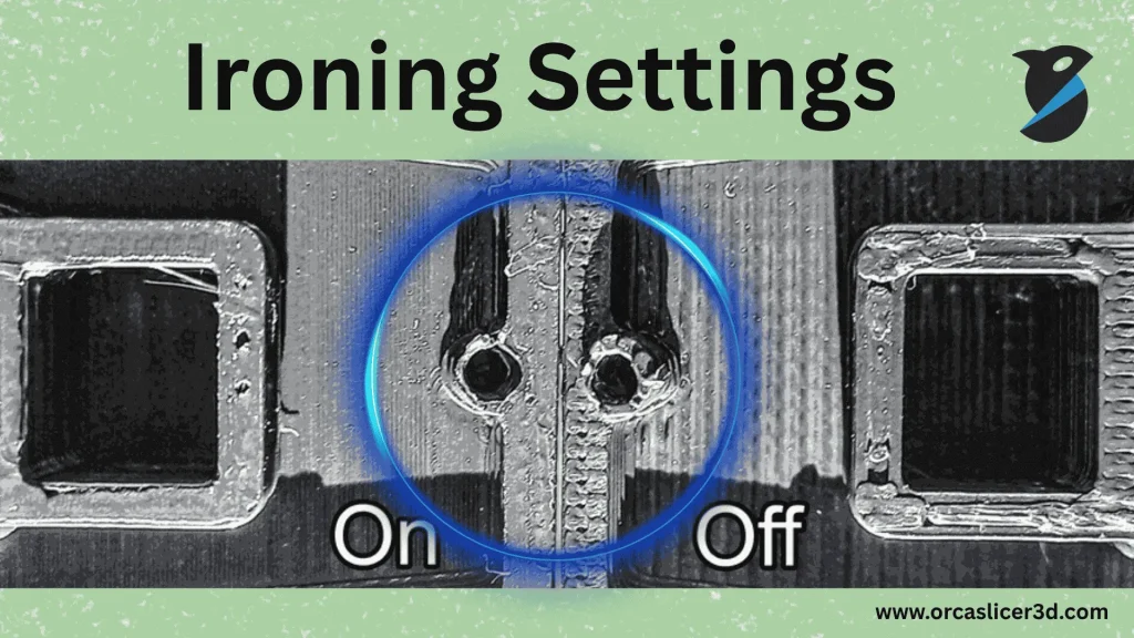
Ironing Settings:
Ironing is a peculiar feature in 3D printing that is aimed at the surface to make it top layer of a model smoother and more glossy.
It does so by printing one more time on the same layer with very low flow and a particular pattern.
That takes out any little gaps in between, and eliminates all bumps for a level glossy surface.
However, ironing ups print time too and if your printer cooling is not good enough it may cause clogs.
Important Note:
During an ironing the filament travels very slowly in the hotend.
This can result in heat buildup, called heat creep and jams.
👉 And remember to check if your printer’s cooling is functioning well when you have ironing enabled.
Type (Which Layers to Iron):
This setting decides which parts of your model will be ironed. You can choose one of the following options:
This value determines which parts of your model will be ironed.
Select any one of the below:
Top Surfaces:
All top surfaces of your print will be ironed.
🔹 Most popular choice for sleek and glossy top surfaces.
Topmost Surface:
You will only iron the petty top layer of your print at the very end.
🔹 For when we only want to smooth the last visible layers.
All Solid Layers:
All solid infill layers (top and inner) will get ironed.
🔹 Provides a totally smooth surface on all solids, but takes extra time.
Pattern:
This setting decides how the ironing lines will be printed.
Common options are:
- Concentric: Circular ironing lines (good for round shapes).
- Rectilinear: Straight parallel lines (good for flat surfaces).
👉 The best pattern is the one that covers the surface most efficiently.
Flow:
This controls how much material is extruded during ironing.
It is set as a percentage of the normal flow rate.
- Lower flow (%) = smoother surface but may leave small gaps.
- Higher flow (%) = better coverage but can cause small bumps or rough spots.
💡 Recommended: Start with a slightly lower flow rate and test your results.
Line Spacing:
This is how far apart each ironing line should be.
If the true minimalistic ef you would like decrease the spacing to your nozzle size or smaller.
This guarantees that it covers, and not just cover but consistently.
Inset:
This controls how far the ironing starts from the model’s edges.
- Inset = 0: Ironing lines reach all the way to the outer edges.
- Inset > 0: Keeps the lines slightly away from edges to avoid extra material buildup.
💡 A small inset helps prevent over-extrusion on the edges.
Angle:
This sets the direction in which ironing is done.
A negative value disables this function and makes ironing follow the same direction as the infill pattern.
Speed:
This controls how fast ironing is performed.
This dictates the speed with which ironing is done.
- Lower speed: more smooth and shiny surface.
- Higher speed: Draft quick but can compromise surface finish.
👉 Adjust the speed depending on how detailed or glossy you want your top layer to be.
Summary:
Ironing is a great way to finish off the top layer of your 3D prints such as on large flat surfaces or visible top surfaces.
It is smoothing your 3D print perfectly and gives you a professional model.
Just keep in mind that flow, spacing and speed all need to be managed, along with good cooling to prevent clogs or heat buildup.
Wall and Surface Quality:
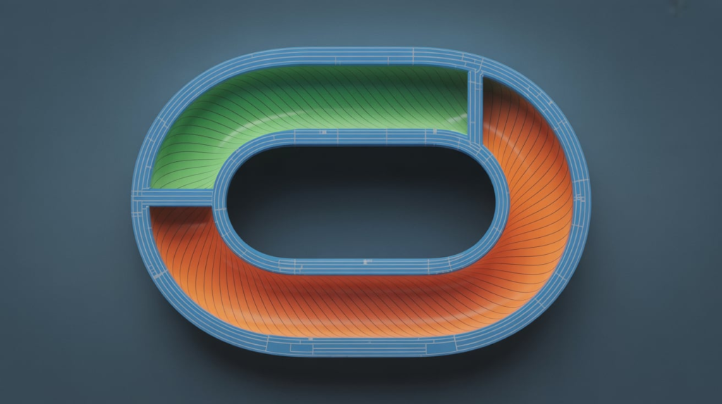
In 3D printing, walls and surface settings play a key role in deciding how strong, smooth, and accurate your print will be. These settings control how the printer builds the inner and outer walls, fills small spaces, and handles travel movements. If adjusted properly, you can achieve better surface finish, higher accuracy, and fewer visual defects.
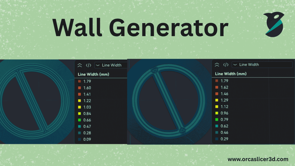
1. Walls Printing Order
This setting controls the sequence in which the printer creates the walls (also called perimeters). The order affects both the strength and the appearance of your print.
- Inner/Outer:
Prints the inner walls first and the outer wall last.
🔹 Best for overhangs, as the outer wall can stick to the inner walls.
🔹 Slightly reduces surface smoothness since the outer wall presses against the inner wall. - Inner/Outer/Inner:
Prints some inner walls, then the outer wall, and then one more inner wall.
🔹 Best for overall accuracy and smooth outer surfaces.
🔹 Needs at least 3 wall loops to work.
🔹 Overhangs may not be as strong but the model looks cleaner. - Outer/Inner:
Prints the outer wall first and the inner wall after it.
🔹 Keeps good surface quality but may cause small visible seams on the outer surface.
2. Print Infill First
When this option is on, the printer prints the infill before the walls.
This can help support walls in parts with overhangs.
However:
- It can push the walls outward, reducing the smoothness of the outside surface.
- It may make the infill pattern visible through the outer wall.
💡 Tip: If you use this option, enable Precise Wall and Inner/Outer/Inner wall order for better results.
3. Wall Loop Direction
This setting defines the direction in which wall loops are printed when viewed from above.
By default, all walls print counterclockwise unless “Reverse on Even” is turned on.
Changing this setting affects how the filament overlaps between layers, which can slightly impact the surface texture.
Note: This feature doesn’t work in spiral vase mode.
4. Surface Flow Ratio
This controls how much filament is used for the top and bottom solid layers.
Lowering this value slightly can make the top surface smoother.
However, before changing it, make sure your printer’s flow calibration is done correctly.
💡 Example: Setting surface flow to 0.95 instead of 1.0 can improve flatness and reduce excess filament buildup.
5. Only One Wall
This option makes the printer use just one wall for flat or narrow top surfaces.
It gives more space for the top infill pattern and is especially useful for small designs like letters or tiny embossed text.
This setting helps avoid unwanted overlaps that can make fine details look messy.
6. Threshold
If a top surface is very small or partly covered by another layer, the printer can ignore it as a “top surface.”
The Threshold setting decides how small that area must be before being ignored.
It can be set in millimeters or as a percentage of the wall width.
💡 Warning: Setting this too high can create visual artifacts on thin parts. If that happens, reduce it or set it to zero.
7. Avoid Crossing Walls
This setting makes the printer avoid traveling directly over walls when moving between sections.
Instead, it takes a short detour around them.
✅ Benefits:
- Reduces surface defects and stringing.
- Improves finish for detailed and decorative parts.
⚠️ Trade-off: It can slightly increase print time but the improvement in print quality is usually worth it.
8. Max Detour Length
This controls how long the detour path can be when avoiding walls.
It can be set in:
- Millimeters (e.g., 5 mm), or
- Percentage of the direct travel distance (e.g., 50%).
If set to 0, there is no limit — the printer can detour as long as needed.
A longer detour means fewer wall crossings but also more printing time.
9. Small Area Flow Compensation
This feature helps the printer handle tiny infill areas more accurately.
In small spaces (like thin text or narrow corners), the printer might extrude too much plastic, causing bumps or blobs.
Flow Compensation automatically adjusts the filament flow rate for those short paths, reducing over-extrusion.
💡 It calculates the correct flow using a flow correction model based on the extrusion length.
10. Flow Compensation Model Example
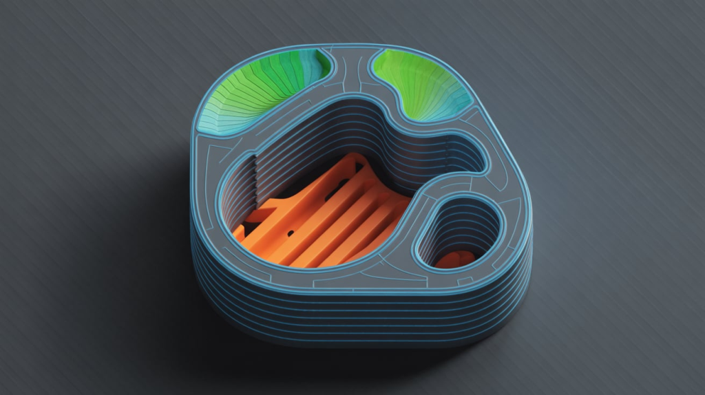
Here’s how a flow correction model might look:
| Extrusion Length (mm) | Flow Correction Factor |
|---|---|
| 0.0 | 0.0 |
| 0.2 | 0.44 |
| 0.4 | 0.61 |
| 0.6 | 0.70 |
| 0.8 | 0.76 |
| 1.5 | 0.85 |
| 2.0 | 0.88 |
| 3.0 | 0.92 |
| 5.0 | 0.95 |
| 10.0 | 1.0 |
The printer uses linear interpolation between these points to calculate smooth changes in flow, ensuring that even very small print features look neat and clean.


Summary
Wall and surface quality settings in Orca Slicer help balance strength, accuracy, and appearance.
Using the right wall order, adjusting flow, and avoiding wall crossings can give you smoother finishes, better overhangs, and cleaner fine details.
Always test different combinations to find what works best for your printer and filament.

Bridging and Overhangs:
Bridging
In 3D printing, bridging means printing material across open gaps or spaces where there is no support underneath. Orca Slicer includes special settings to help reduce sagging, improve the look of top layers, and make sure bridges stay strong and even.
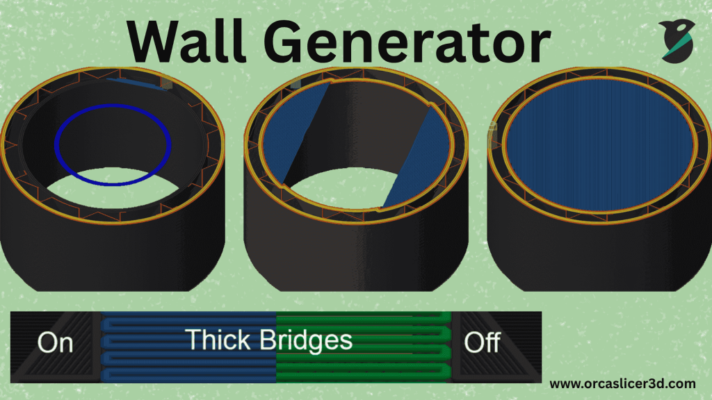
1. Flow Ratio
This setting controls how much plastic is pushed through the nozzle while printing bridges.
Reducing this value slightly (for example, to 0.9) helps prevent sagging because less material is used.
The final bridge flow is calculated by multiplying this value by the filament’s flow rate and the object’s flow ratio (if set).
💡 Tip: Start with 0.9 or 0.95 for most materials to balance flow and bridge strength.
2. Bridge Density
Bridge density defines how thick the bridge layer will be. It is especially important for the first layer printed over infill or gaps.
Decreasing it slightly (e.g., 0.9) can give smoother top surfaces above infill.
The actual bridge density is multiplied by both the flow and filament ratios.
✅ Lower density = smoother surface
⚠️ Too low = weak bridges
3. Thick Bridges
When this option is turned on, the slicer prints bridges with extra thickness to make them stronger and less likely to break when spanning large gaps.
✅ Improves reliability and allows longer bridges.
⚠️ May produce a rougher underside surface.
Recommendation: Keep it enabled for internal bridges to increase strength and reduce sagging.
4. Extra Bridge Layers
This adds an additional bridge layer above existing bridges.
The extra layer makes bridges stronger and smoother, especially useful for high-speed printers.
Options include:
- Disabled: No second bridge layer (default).
- External bridge only: Adds an extra layer only on outside bridges.
- Internal bridge only: Adds an extra layer on bridges inside the model (helps top surfaces).
- Apply to all: Adds extra layers to both internal and external bridges.
💡 Recommended: Use External bridge only for a clean balance of speed and strength.
5. Filter Out Small Internal Bridges
Small bridges inside the model may not always be necessary.
Filtering them out speeds up printing and prevents issues like pillowing or curling.
You can choose between:
- Filter: Default mode, skips small bridges.
- Limited filtering: Adds bridges only on steep slopes.
- No filtering: Creates bridges everywhere possible — useful for complex or slanted models but may slow printing.
6. Bridge Counterbore Hole
When printing counterbore holes (flat-bottomed holes), the top layer can sag.
This setting creates bridges over those holes to prevent drooping.
You can select:
- None: No bridge added.
- Partially Bridged: Covers only part of the hole to support the next layer.
- Sacrificial Layer: Builds a full bridge layer that is removed after printing, giving a perfectly flat surface.
💡 Recommended: Use “Partially Bridged” for balance between quality and print time.
Overhangs:
Definition
Fluff perimeters are those details of a print which hang out beyond the level below.
These are sometimes a little difficult to print, because they don’t have much under-support.
Special, overhang controls in Orca Slicer to print steeper angles cleanly and with accuracy.
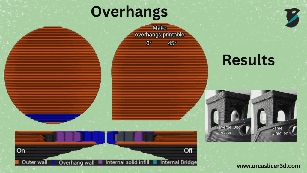
Detect Overhang Wall
This feature is used to sense areas of the print that overhangs and then set speed or bridge settings automatically for those specific area.
It minimizes droopy edges and uneven layers, increasing the print quality.
Make Overhang Printable
In this case, Orca Slicer slightly changes your 3D model geometry to make super extreme overhangs printable without support material.
How much the slicer will alter can be controlled with the Maximum Angle slider.
Maximum Angle
This is the degree of steepness at which it has to add on support.
- 90°: No change — spits out everything as-is.
- 0°: Replaces overhangs with supported material at an angle (most conservative).
- 45°–60°: Ideal For Most Printers And Models.
💡 Example: If set at 50°, overhangs can be slightly steeper without sacrificing print quality.
Hole Area
Specifies the maximum hole size in the base that can be filled automatically with conical support.
A setting of 0 would remove all holes, and as the value increases, larger open spaces are retained.
Extra Perimeters on Overhangs
When activated, the slicer includes additional walls on steep overhangs.
This gives the overhang areas more strength, and helps them adhere to the rest of the model.
✅ Improves print reliability
⚠️ Print time might be slightly increased
Reverse on Even
This is reversing the print direction on every other layer.
By alternating the direction it may help to even out the stress between layers and can improve overhang quality (though this is more applicable for materials that warps easily, like ABS, ASA, TPU or Silk PLA).
💡 Tip: III To achieve best results, set the Reverse Threshold to 0 so every even layer changes direction.
Reverse Internal Only
If you are looking for smoother outer walls but still don’t want to compromise the advantages of alternating directions, switch Reverse Internal Only on.
It only reverses the inner walls, leaving the outer wall printed in a single direction — perfect for keeping one side of your print looking nice.
Reverse Threshold
It determines how much overhang is needed before their reversal occurs.
You can set it as:
- 0: Reverse all layers.
- mm: A fixed distance.
- %: Porcentaje de anchura total del muro.
⚠️ If not set properly, it could result in uneven textures. Use it only if overhang reversal definitely make the print better.
Summary
Support and Overhang REDUCTION: It can make printers transfer hard shapes without the need for support.
Bridging: Here you control how your printer bridges gaps, and thus avoid like drooping and neatly covered surfaces.
Overhang settings determine the angle at which material doesn’t stretch or sag while printing, for better looks and structure.
When tuned well, such features can help your prints achieve stronger bridges, cleaner curves and better overhangs – even on difficult models.
