Printer Configuration and Hardware Setup | Orca Slicer
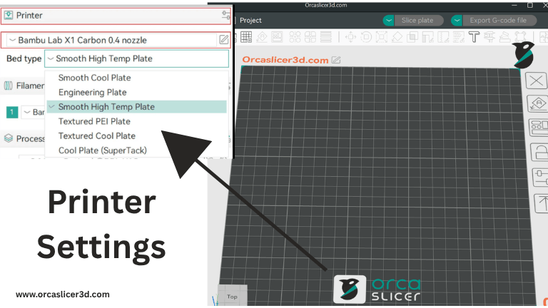
Setting up your 3D printer correctly is the foundation of achieving high-quality prints. Each hardware component — from the fans and heater to the bed and mesh calibration — plays a crucial role in the final result. In Orca Slicer, you can control and fine-tune these hardware systems directly within the slicer interface, without needing external software or manual firmware edits.
This guide will walk you through the complete Printer Configuration and Hardware Setup in Orca Slicer, including how to manage air filtration and exhaust fans, configure auxiliary cooling, maintain chamber temperature, calibrate with Adaptive Bed Mesh, and select from different bed types for various materials.
By the end, you’ll understand how to synchronize your slicer and firmware (like Klipper or Marlin) for smooth, automated, and efficient 3D printing — every time.
(Air Filtration / Exhaust Fan Handling)
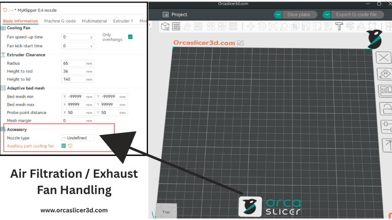
A 3D printer is made up of several hardware components that work together to ensure a successful print. One of the most important systems among them is air filtration — it helps maintain the temperature inside the printing chamber while removing toxic fumes generated during printing. Without a proper air-filtration setup, prints can suffer from poor adhesion, warping, or even unsafe air quality.
You don’t need separate software to control every part of your printer. With Orca Slicer, you can manage all these hardware components, including the exhaust and auxiliary fans, directly through slicer commands.
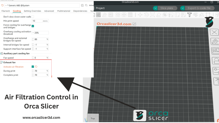
Air Filtration Control in Orca Slicer
OrcaSlicer uses a standard G-code command system for controlling fans. Specifically, the slicer sends commands like M106 (turn a fan on / set speed) and M107 (turn a fan off).
Each fan in the printer is identified by an index called P, and the speed of each fan is controlled using S (which ranges from 0–255, equivalent to 0–100% in the slicer UI).
Here’s how OrcaSlicer maps the fan indexes:
- P0: Part Cooling Fan (main layer fan)
- P1: Additional fan (if available)
- P2: Auxiliary / CPAP / Booster fan
- P3: Exhaust / Enclosure fan
Key Command Used:
OrcaSlicer uses M106 P3 to control the air-filtration or exhaust fan.
Step-by-Step: How to Set Up Air Filtration / Exhaust Fan in OrcaSlicer
Step 1: Open Printer Settings
- In OrcaSlicer, go to Printer Settings.
- Under the General or Advanced tab (depending on version), look for options related to Auxiliary or Exhaust Fans.
- Enable these features if they are turned off.
Step 2: Adjust Fan Speed in Material Settings
- Navigate to Filament (Material) Settings → Cooling Tab.
- Set your desired Auxiliary Fan and Exhaust Fan speeds in percentages (0–100%).
- OrcaSlicer will automatically translate these values into G-code commands (e.g.,
M106 P3 S128for ~50% fan speed).
This ensures your printer receives the correct commands each time you start a print — no manual intervention is needed.
Setting Up Macros in Klipper (Firmware Configuration)
If you are using Klipper firmware, you can automate these commands through macros. This allows you to control multiple fans (part cooling, auxiliary, exhaust) using one unified setup.
Concept of Keys and G-code
M106→ Activates fan(s) and sets speedM107→ Turns fan(s) offP→ Selects which fan (P0–P3)S→ Controls speed (0–255)
So, for example:
M106 P2 S200→ Runs the Auxiliary Fan at ~80%M106 P3 S128→ Runs the Exhaust Fan at 50%
Klipper Basic Configuration (Simple Index Mapping)
Below is a reference configuration for Klipper users. It defines how each fan is mapped to OrcaSlicer’s P indexes.
# Part Cooling Fan (P0)
[fan_generic fan0]
pin: PA7
cycle_time: 0.01
hardware_pwm: false

# Auxiliary Fan (P2)
[fan_generic fan2]
pin: PA8
cycle_time: 0.01
hardware_pwm: false

# Exhaust / Enclosure Fan (P3)
[fan_generic fan3]
pin: PA9
cycle_time: 0.01
hardware_pwm: false

[gcode_macro M106]
gcode:
    {% set fan = 'fan' + (params.P|int if params.P is defined else 0)|string %}
    {% set speed = (params.S|float / 255 if params.S is defined else 1.0) %}
    SET_FAN_SPEED FAN={{fan}} SPEED={{speed}}

[gcode_macro M107]
gcode:
    {% if params.P is defined %}
        {% set fan = 'fan' + (params.P|int)|string %}
        SET_FAN_SPEED FAN={{fan}} SPEED=0
    {% else %}
        SET_FAN_SPEED FAN=fan0 SPEED=0
        SET_FAN_SPEED FAN=fan2 SPEED=0
        SET_FAN_SPEED FAN=fan3 SPEED=0
    {% endif %}
Note:
Always change the pin: numbers to match your printer’s actual board pinout.
Advanced Option (Index ⇄ Name Mapping)
For users who prefer meaningful fan names (like “CPAP” or “EXHAUST”), you can create a fan_map to translate OrcaSlicer’s numeric values into human-readable names.
This method is especially helpful if you rewire your printer or repurpose a fan — you just update the map once without changing slicer output.
[fan_generic CPAP]        # Orca P0
pin: PB7
max_power: 0.8
shutdown_speed: 0
kick_start_time: 0.100
cycle_time: 0.005
hardware_pwm: False
off_below: 0.10

[fan_generic EXHAUST]     # Orca P3
pin: PE5
cycle_time: 0.01
hardware_pwm: False
off_below: 0.2

[gcode_macro M106]
description: "Set fan speed (Orca compatible)"
gcode:
    {% set fan_map = { 0: "CPAP", 3: "EXHAUST" } %}
    {% set p = params.P|int if 'P' in params else 0 %}
    {% set fan = fan_map[p] if p in fan_map else fan_map[0] %}
    {% set speed = (params.S|float / 255 if 'S' in params else 1.0) %}
    SET_FAN_SPEED FAN={{fan}} SPEED={{speed}}

[gcode_macro M107]
description: "Turn off fans. No P = all, P# = specific"
gcode:
    {% set fan_map = { 0: "CPAP", 3: "EXHAUST" } %}
    {% if 'P' in params %}
        {% set p = params.P|int %}
        {% if p in fan_map %}
            SET_FAN_SPEED FAN={{fan_map[p]}} SPEED=0
        {% else %}
            RESPOND PREFIX="warn" MSG="Unknown fan index P{{p}}"
        {% endif %}
    {% else %}
        {% for f in fan_map.values() %}
            SET_FAN_SPEED FAN={{f}} SPEED=0
        {% endfor %}
    {% endif %}
Quick Customization Tips
- You can add or remove entries in
fan_mapdepending on the fans used by your printer. - Tune parameters like
max_power,off_below, orcycle_timeto optimize for your fan type (e.g., CPAP blowers vs. axial exhaust fans). - Keep comments like
# Orca P3next to each[fan_generic]for easy reference later.
Usage Examples
- Full Cooling:
M106 P0 S255→ Runs part cooling fan at 100% - Exhaust Half Speed:
M106 P3 S128→ Runs exhaust at ~50% - Turn Off One Fan:
M107 P3→ Stops only the exhaust - Turn Off All Fans:
M107 - Manual Override (Klipper Console):
SET_FAN_SPEED FAN=CPAP SPEED=0.7
Important Things to Remember
- In Klipper-based printers, OrcaSlicer’s
M106 P2usually maps to the Auxiliary Fan, andM106 P3to the Exhaust Fan. - Always verify your pin configurations before running prints.
- Adjust your S value (0–255) for the correct speed — Orca automatically translates this from percentage.
- Each filament profile can have its own auxiliary or exhaust fan settings in the Filament → Cooling tab.
Air-filtration and exhaust fan control in OrcaSlicer ensure a balanced environment for printing high-quality models. By understanding how G-code commands interact with firmware macros, you can automate and fine-tune airflow management across different materials and print conditions.
(Auxiliary Fan Settings)
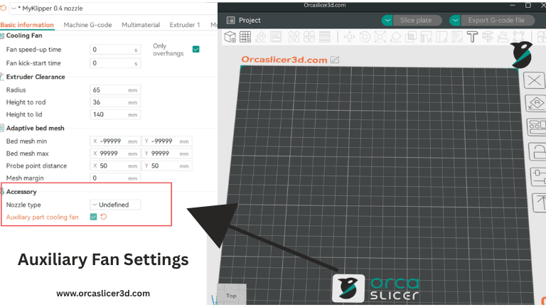
Auxiliary fans (often CPAP/booster blowers) add targeted airflow around the extrusion path for cleaner bridges, crisper overhangs, and more consistent layer cooling—especially on fast prints or high-temp materials. In Orca Slicer, auxiliary cooling is handled with the same standard fan G-code as other fans, so you don’t need extra tools or plugins.
What OrcaSlicer Sends (Quick Primer)
M106→ turn a fan on / set speedM107→ turn a fan offP(fan index) commonly maps as:- P0 = Part cooling (layer) fan
- P1 = Additional fan (if present)
- P2 = Aux / CPAP / Booster (typical)
- P3+ = Exhaust / Enclosure (commonly)
S= speed 0–255 (Orca UI shows this as 0–100%)
Set It Up in OrcaSlicer (Step-by-Step)
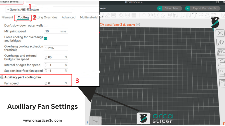
Step 1 — Enable at the printer level
- Open Printer Settings → Basic Information (or General/Advanced, depending on version).
- Enable or expose Auxiliary Fan controls.
Step 2 — Tune per filament
- Go to Filament (Material) Settings → Cooling.
- Set Auxiliary Fan percentage for each material profile (e.g., higher for PLA overhangs, lower or off for ABS in an enclosure).
- OrcaSlicer will emit
M106 P2 S###(or whatever index you map) automatically during the print.
Tip: Use different Aux settings for different materials and nozzle sizes. High flow/high temp profiles often benefit from a short burst of Aux on bridges only.
Also Read: Filament Profiles
Klipper Firmware: Two Clean Ways to Map the Aux Fan
Option A — Simple (Index-only → fan0, fan2, fan3)
Use when you’re fine with numeric indexes:
# P0 → part cooling
[fan_generic fan0]
pin: PA7
cycle_time: 0.01
hardware_pwm: false

# P2 → auxiliary (CPAP/booster)
[fan_generic fan2]
pin: PA8
cycle_time: 0.01
hardware_pwm: false

# P3 → exhaust (if present)
[fan_generic fan3]
pin: PA9
cycle_time: 0.01
hardware_pwm: false

[gcode_macro M106]
gcode:
    {% set fan = 'fan' + (params.P|int if params.P is defined else 0)|string %}
    {% set speed = (params.S|float / 255 if params.S is defined else 1.0) %}
    SET_FAN_SPEED FAN={{fan}} SPEED={{speed}}

[gcode_macro M107]
gcode:
    {% if params.P is defined %}
        {% set fan = 'fan' + (params.P|int)|string %}
        SET_FAN_SPEED FAN={{fan}} SPEED=0
    {% else %}
        SET_FAN_SPEED FAN=fan0 SPEED=0
        SET_FAN_SPEED FAN=fan2 SPEED=0
        SET_FAN_SPEED FAN=fan3 SPEED=0
    {% endif %}
Option B — Advanced (Index ⇄ Name mapping)
Best if you want readable names and easy rewiring later:
# Orca P0 → CPAP (part/booster blower)
[fan_generic CPAP]
pin: PB7
max_power: 0.8
shutdown_speed: 0
kick_start_time: 0.100
cycle_time: 0.005
hardware_pwm: False
off_below: 0.10

# Orca P3 → EXHAUST (example shown for completeness)
[fan_generic EXHAUST]
pin: PE5
cycle_time: 0.01
hardware_pwm: False
off_below: 0.2

[gcode_macro M106]
description: "Set fan speed (Orca compatible)"
gcode:
    {% set fan_map = {
        0: "CPAP",      # Orca P0
        3: "EXHAUST",   # Orca P3
        # 2: "AUX",     # Uncomment if you define AUX as a separate device
    } %}
    {% set p = params.P|int if 'P' in params else 0 %}
    {% set fan = fan_map[p] if p in fan_map else fan_map[0] %}
    {% set speed = (params.S|float / 255 if 'S' in params else 1.0) %}
    SET_FAN_SPEED FAN={{fan}} SPEED={{speed}}

[gcode_macro M107]
description: "Turn off fans. No P = all, P# = specific"
gcode:
    {% set fan_map = { 0: "CPAP", 3: "EXHAUST" } %}
    {% if 'P' in params %}
        {% set p = params.P|int %}
        {% if p in fan_map %}
            SET_FAN_SPEED FAN={{fan_map[p]}} SPEED=0
        {% else %}
            RESPOND PREFIX="warn" MSG="Unknown fan index P{{p}}"
        {% endif %}
    {% else %}
        {% for f in fan_map.values() %}
            SET_FAN_SPEED FAN={{f}} SPEED=0
        {% endfor %}
    {% endif %}
Always update
pin:to your board’s actual pins.
CPAP/booster blowers may need different PWM behavior—tunemax_power,off_below,cycle_time, andkick_start_timefor smooth low-speed starts.
Practical Usage Examples
- Max Aux for bridging:
M106 P2 S255(100% Aux) - Gentle Aux:
M106 P2 S128(~50%) to avoid over-cooling ABS/ASA - Turn Aux off:
M107 P2 - Manual override (Klipper console):
SET_FAN_SPEED FAN=CPAP SPEED=0.7
Pro Tips (from both sources, distilled)
- In many Klipper setups, Orca’s
P2is the Aux fan andP3is Exhaust—but don’t assume: confirm your wiring and pin mapping. - Keep comments like
# Orca P2next to each[fan_generic]so future changes are painless. - Make Aux material-aware: higher for PLA bridges; moderate for PETG; low/off for ABS in a sealed chamber.
- If Aux causes surface frosting or layer brittleness, reduce S or limit to bridges/overhangs via filament cooling rules.
(Chamber Temperature Control)
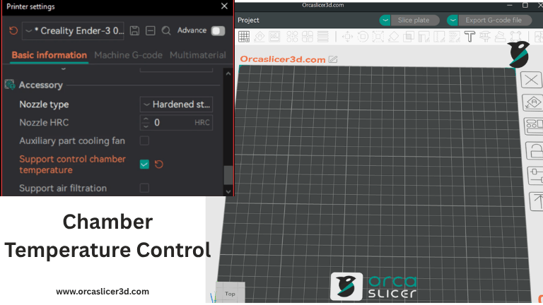
Maintaining a consistent chamber temperature is crucial for dimensional accuracy and warp-free prints, especially with ABS/ASA/PA and fiber-filled filaments. OrcaSlicer can control an active chamber heater directly via standard G-code, so you don’t need extra tools or scripts.
What OrcaSlicer Sends (Quick Primer)
M141/M191— chamber heater control (active chamber heating)- If both are enabled:
- Filament → Activate temperature control
- Printer → Support control chamber temperature
then OrcaSlicer auto-insertsM191at the start of your G-code (before “Machine G-code”) to pre-heat the chamber.
- If your machine has an auxiliary fan, OrcaSlicer can automatically run it during heat-up to circulate warm air in the chamber.
Set It Up in OrcaSlicer (Step-by-Step)
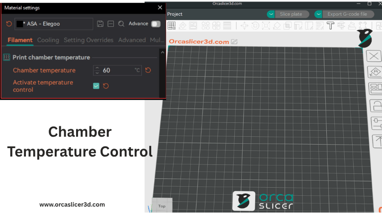
Step 1 — Enable control flags
- Open Filament Settings → (Cooling / Temperature) and enable Activate temperature control for that filament.
- Open Printer Settings and enable Support control chamber temperature.
Step 2 — Let Orca handle pre-heat
- With both flags ON, Orca adds
M191at the start of the print to heat and wait until the chamber meets target.
Step 3 — (Optional) Manual control in Machine G-code
If you want to set chamber setpoints yourself, you can reference Orca’s variables:
; Use the first filament’s chamber temperature
M191 S{chamber_temperature[0]}

; Or the highest setpoint across all loaded filaments
M191 S{overall_chamber_temperature}
Klipper Reference Configuration (Active Chamber Heater)
Important: Replace all
pin:and sensor entries with your actual hardware. Use your real chamber sensor (not a random PTC) and tune PID safely.
[heater_generic chamber_heater]
heater_pin: PB10
max_power: 1.0
# Use the actual chamber temperature sensor (example below)
sensor_type: NTC 100K MGB18-104F39050L32
sensor_pin: PA1
control: pid
pid_Kp: 63.418
pid_ki: 0.960
pid_kd: 1244.716
min_temp: 0
max_temp: 70

[gcode_macro M141]
gcode:
    SET_HEATER_TEMPERATURE HEATER=chamber_heater TARGET={params.S|default(0)}

[gcode_macro M191]
gcode:
    {% set s = params.S|float %}
    {% if s == 0 %}
        # If target is 0, do nothing
        M117 Chamber heating cancelled
    {% else %}
        SET_HEATER_TEMPERATURE HEATER=chamber_heater TARGET={{s}}
        # Optional: assist heating with bed (uncomment if desired)
        # M140 S100
        TEMPERATURE_WAIT SENSOR="heater_generic chamber_heater" MINIMUM={{s-1}} MAXIMUM={{s+1}}
        M117 Chamber at target temperature
    {% endif %}
Usage Examples
- Preheat to filament’s first profile value
M191 S{chamber_temperature[0]} - Preheat to the max of all filaments in the job
M191 S{overall_chamber_temperature} - Manual fixed target (e.g., 50 °C)
M141 S50(set) →M191 S50(set & wait)
Tip: For ABS/ASA, start prints only after
M191completes; this reduces first-layer lift and improves inter-layer bonding.
Pro Tips (Merged from both sources)
- Let Orca drive: With the two checkboxes enabled, Orca will insert
M191automatically so you don’t forget chamber pre-heat. - Air circulation during heat-up: If you have an auxiliary fan, Orca can spin it automatically while heating to even out chamber temperature.
- Safety & tuning: Start with conservative targets (e.g., 40–50 °C) and verify with an external thermometer. Increase gradually to avoid overheating electronics.
- Sensor correctness: Ensure the sensor type and location truly reflect chamber air temperature (not bed or toolhead).
- Consistency: Pair chamber pre-heat with enclosure/exhaust control; avoid running exhaust at high speed during heat-up or you’ll pull heat out.
(Adaptive Bed Mesh)
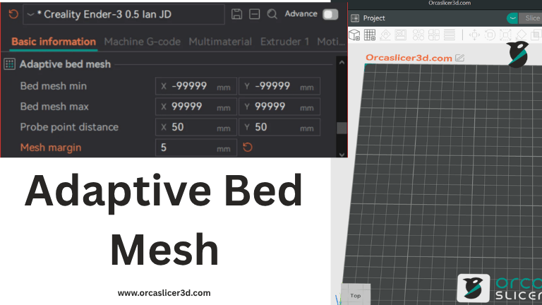
An Adaptive Bed Mesh (ABM) is a smart probing method that focuses only on the actual print area instead of scanning the entire build plate.
In simple terms — if you’re printing a small cup, only the footprint of the cup’s base is probed and meshed. This saves time, improves first-layer accuracy, and speeds up the print preparation process.
Unlike static full-bed leveling, adaptive bed meshing dynamically adjusts the mesh area based on each print’s position and size, giving you precision leveling exactly where it’s needed.
Why Adaptive Bed Mesh Matters
Without adaptive meshing, the printer spends extra time probing the full surface even when printing small parts — wasting time and introducing potential inconsistencies.
With OrcaSlicer’s built-in ABM, you can:
- Improve first-layer adhesion
- Reduce warping and uneven extrusion
- Save time by probing only the print footprint area
- Integrate bed mesh commands directly into your Machine Start G-code
Best of all, OrcaSlicer’s implementation works natively with Marlin, Klipper, and RepRapFirmware (RRF) — no plugins, no extra firmware changes required.
How to Configure Adaptive Bed Mesh in OrcaSlicer
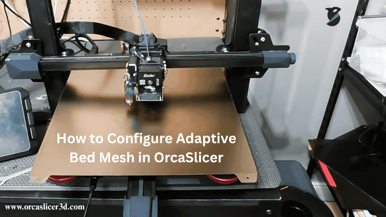
Step 1 – Open Bed Mesh Settings
Go to Printer Settings → Basic Information, and look for Adaptive Bed Mesh (ABM) options.
Here, you can configure min/max mesh limits, probe spacing, and mesh margins.
Step 2 – Define Mesh Range
- Bed mesh min:
Defines the minimum probing point on your bed.
Most printers can’t probe the entire surface due to XY offsets, so this setting ensures the probe never moves outside printable bounds.
Default:(-99999, -99999)— meaning no restriction (full-bed probing). - Bed mesh max:
Defines the maximum probing area for the bed mesh.
Default:(99999, 99999)— meaning no restriction.
You can set tighter boundaries if your probe can’t reach bed corners.
Step 3 – Probe Point Distance
Determines the grid spacing between probe points along the X and Y axes.
Default: 50 mm (adjust for finer or coarser meshes depending on your bed size).
Step 4 – Mesh Margin
Adds a buffer area beyond the print’s footprint.
Note (for Klipper users): OrcaSlicer already handles margins internally, so always set margin = 0 in your Klipper configuration or pass
ADAPTIVE_MARGIN=0when calling the calibration command.
G-Code Variables for Adaptive Bed Mesh
OrcaSlicer automatically calculates and inserts the following variables into your start G-code:
| Variable | Description |
|---|---|
bed_mesh_probe_count | Number of probe points (X,Y) based on area and probe spacing |
adaptive_bed_mesh_min | Starting (min) coordinates of the adaptive mesh |
adaptive_bed_mesh_max | Ending (max) coordinates of the adaptive mesh |
bed_mesh_algo (or ALGORITHM) | Interpolation algorithm: lagrange (if probe count < 4) or bicubic (default for denser meshes) |
Example G-code Integration (per Firmware)
Marlin
Marlin doesn’t support specifying probe counts yet, so only area-based probing is possible:
; Adaptive Bed Mesh for Marlin
G29 L{adaptive_bed_mesh_min[0]} R{adaptive_bed_mesh_max[0]} \
   F{adaptive_bed_mesh_min[1]} B{adaptive_bed_mesh_max[1]} T V4
Klipper
Klipper supports a fully adaptive probe area with variable density and algorithm control:
; Adaptive Bed Mesh for Klipper
; Orca handles adaptive margins internally
; Set ADAPTIVE=0 to use Orca’s mesh logic (not Klipper’s)
BED_MESH_CALIBRATE \
  mesh_min={adaptive_bed_mesh_min[0]},{adaptive_bed_mesh_min[1]} \
  mesh_max={adaptive_bed_mesh_max[0]},{adaptive_bed_mesh_max[1]} \
  ALGORITHM=[bed_mesh_algo] \
  PROBE_COUNT={bed_mesh_probe_count[0]},{bed_mesh_probe_count[1]} \
  ADAPTIVE=0 ADAPTIVE_MARGIN=0
RepRapFirmware (RRF)
; Adaptive Bed Mesh for RRF
M557 X{adaptive_bed_mesh_min[0]}:{adaptive_bed_mesh_max[0]} \
     Y{adaptive_bed_mesh_min[1]}:{adaptive_bed_mesh_max[1]} \
     P{bed_mesh_probe_count[0]}:{bed_mesh_probe_count[1]}
Key Tips for Best Results
Keep probe distance moderate (40–60 mm) for balance between accuracy and speed.
- Ensure your min/max mesh points don’t exceed your printer’s physical limits.
- For Klipper, always keep
ADAPTIVE_MARGIN=0. - For Marlin, fine-tune probing speed and count using firmware’s leveling menu.
- The algorithm automatically adjusts for print area size — “lagrange” for small regions and “bicubic” for large grids.
(Bed Types)
In 3D printing, the choice of bed type directly affects adhesion, surface finish, and print reliability. Different filaments require different surface textures and temperature ranges to achieve perfect first-layer bonding.
To simplify this process, OrcaSlicer allows you to configure and switch between multiple bed types directly from the slicer, ensuring every material is printed on its ideal surface without manual adjustments.
What “Multiple Bed Types” Mean
In OrcaSlicer, enabling Multiple Bed Types lets you define and store different print surface configurations — each with its own temperature and offset values.
For example, you might use:
- A Cool Plate for PLA or PETG,
- An Engineering Plate for ABS or ASA,
- A High-Temp Plate for PC or Nylon, and
- A Textured PEI Plate for flexible filaments or aesthetic finishes.
Each type has its own thermal characteristics and surface grip — and OrcaSlicer automatically applies the correct bed temperature and offset for your selected bed type.
How to Enable and Configure Multiple Bed Types in OrcaSlicer
Step 1 – Enable Multiple Bed Support
- Open OrcaSlicer.
- Navigate to Printer Settings → Basic Information.
- Turn ON the option “Multiple Bed Types.”
Step 2 – Choose and Configure Bed Type
- Once enabled, go to the “Bed Type” dropdown menu.
- Select your desired surface type (e.g., “Textured PEI Plate”).
- OrcaSlicer automatically loads or lets you adjust the bed temperature specific to that plate.
Step 3 – Customize Filament Temperature per Bed Type
- Open Filament Settings → Temperature.
- For each filament profile, you can set unique bed temperatures for every bed type.
- Orca will automatically apply the matching temperature during slicing.
Using curr_bed_type in Custom G-code
OrcaSlicer supports the curr_bed_type variable — a powerful feature that allows your printer’s firmware (like Klipper) to detect which bed type is currently selected and make real-time G-code adjustments.
For example, if you need to tweak the Z-offset slightly depending on your build plate’s thickness or texture, you can use the following snippet:
{if curr_bed_type=="Textured PEI Plate"}
  SET_GCODE_OFFSET Z=-0.05
{else}
  SET_GCODE_OFFSET Z=0.0
{endif}
Note:This ensures that the nozzle always maintains the perfect first-layer distance — no matter which bed you’re printing on.
Available Bed Types in Orca Slicer
OrcaSlicer currently supports the following built-in bed types:
- “Cool Plate” – For low-temp materials like PLA, PETG, and TPU.
- “Engineering Plate” – For technical filaments like ABS and ASA.
- “High Temp Plate” – Designed for high-performance materials such as Nylon and Polycarbonate.
- “Textured PEI Plate” – Excellent for flexible filaments or parts requiring smooth bottom finishes.
A perfectly configured printer doesn’t just deliver better print quality — it makes your 3D printing process smarter, faster, and more reliable. With Orca Slicer, you can manage everything from fan speeds and air filtration to bed mesh calibration and temperature control, all within one cohesive platform.
Whether you’re printing delicate PLA parts or engineering-grade Nylon, setting up your printer hardware correctly ensures consistent results and minimal manual intervention. Take the time to configure each section — fans, chamber, mesh, and bed type — once, and enjoy effortless printing across all your future projects.
